CADFEM – Driving Force of Simulation since 1985
Since the company was founded, we have been a close sales partner of Ansys, the world‘s largest developer of simulation software. We distribute Ansys software products and support Ansys users in all questions of simulation, from advice on getting started and expanding, training and further education and hotline support to project work, software customisation and the provision of the optimal hardware or cloud platform. In addition to many other application areas of simulation such as mechanics, fluid dynamics or electromagnetism, we also support our customers in the area of optical simulation. Here, an optical simulation is only as good as the description of the material on which it is based. In order to characterise the materials entering the optical simulation in the best possible way, CADFEM operates an optical laboratory in Grafing. Here, the reflection and transmission properties of the materials to be characterised are measured with the help of a goniometer and the scattering behaviour is analysed. Together with a spectral measurement of the reflection and transmission, material models are then built from the acquired data for use in the Ansys SPEOS software.

About CADFEM
A successful family business since 1985
As a family-owned company, CADFEM has been providing decisive impetus to successfully continue the history of numerical simulation in development and design since 1985. We have developed into one of the leading providers of simulation solutions worldwide. Strong engineering competence with a high level of practical experience and far-sighted consulting with a good sense of the market and trends are what distinguish us.

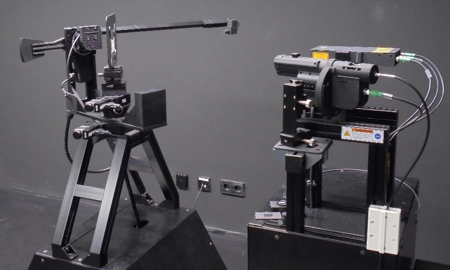
Goniometer for scattered light measurement
Our customers can be confident of the highest quality material models, as we extensively validate each material before it is delivered.
For this purpose, we have an optical bench on which we illuminate the materials with a known LED at different angles and distances and record luminance images.
We have replicated this optical bench in Ansys SPEOS. We simulate exactly the luminance image that we have recorded on the optical bench. Only when the deviations between the simulation and the real image meet certain criteria do we release the material.
If this is not the case, the cause of the deviation must be sought and eliminated.
One possible cause of deviations can be insufficient characterisation of the LED used. For example, in addition to the light distribution of the LED used, the exact spectrum depending on the emission angle plays a decisive role. In the case of white phosphor conversion LEDs, the spectrum usually changes with the emission angle because the rays have a longer path through the phosphor when the light is emitted to the side. For this reason, it is important to know the spectrum of the LED as a function of the emission angle.

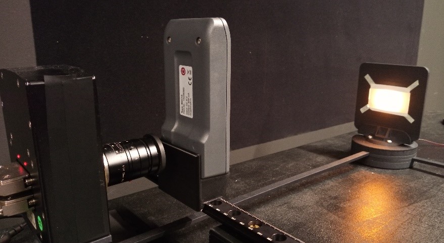
MSC15 set up in front of the luminance camera to check the transmission spectrum.
With the help of the MSC15 handheld spectrometer, we now have a simple and straightforward way to better characterise our light sources and thus improve validation. Furthermore, we can check the reflection and transmission spectra of the materials on our bench and compare them with the simulated data.
With the MSC15, we have a good tool to further increase the quality of the optical properties of the materials and to provide our customers with high-quality material models.

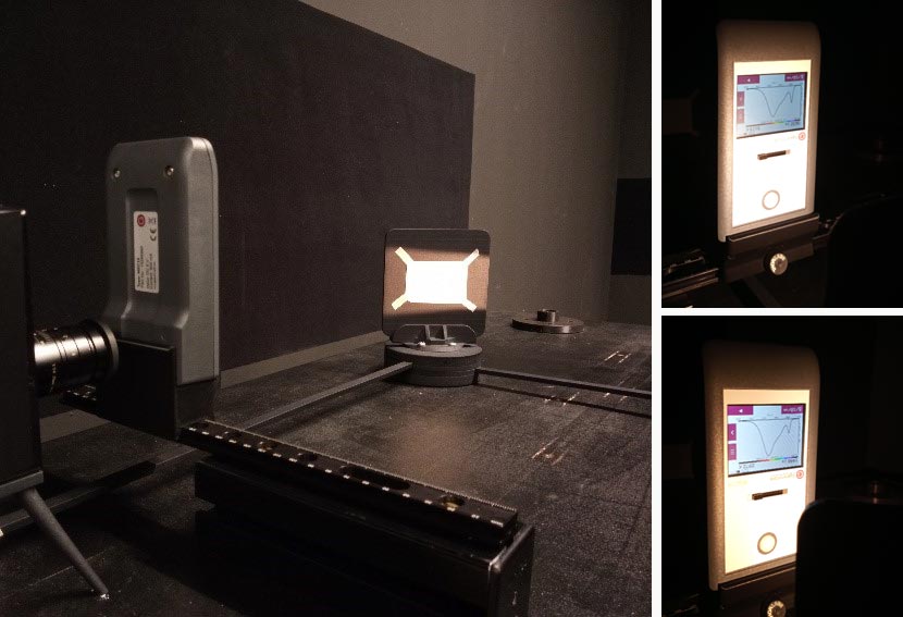
Left: Material illuminated from the side to check the reflection spectrum. Right: Spectrometer directly in front of the LED to characterize the Source. Top right; directly in front of the LED, bottom right; with 45° rotated LED.
At a glance
- Material models of the highest quality
- Simple and straightforward way to better characterize light sources and improve validation
- Control of the reflection and transmission spectra of the materials on the optical bench
- Comparison with simulated data
- Very high absolute measurement accuracy, true to the vision: Enabling Accuracy!
- MSC15 - Compact hand-held measuring device